Friday, November 27, 2020

Comparison of Different types of Microcontroller

The comparison of different types of microcontroller with their features like speed, RAM and ROM size, applications, cost, types of interface, source of clock etc.... has been discussed in below table. 

Features

Microcontroller

8051

AVR

ARM

PIC

Speed

60 MHZ

0 to 20 MHz

1.9 DMIPS/MHz

252 MHz core speed

Source of the clock

12    clock/instruction cycle

1 clock/instruction cycle

1 clock/instruction cycle

4 clock/instruction cycle

ROM Size

4 KB

256 KB

512 KB

4 KB – 128 KB

RAM Size

128 bytes

32 bytes

96 KB

256-4096 bytes

Cost

Rs. 513 per piece

Rs. 999 per piece

Rs. 450 per piece

Rs. 100 per piece

Applications

  1.   Robotics, GPS, GSM based projects applications
  2. Controlling remote industrial plant using SCADA


Specially designed to use in hobbyist and educational applications

Digital TVs, set-up boxes, smartphones, mobile, and laptops, etc.…

It is used in peripherals, audio accessories, games, etc.…

Types of Interface

UART, USART, SPI, I2C, etc.….

UART, USART, LIN, I2C, SPI, CAN, USB, Ethernet, etc.…

UART, USART, SPI, CAN, USB, Ethernet, DSP, Serial Audio Interface (SAI), etc.….

UART, USART, PIC, LIN, CAN, I2S, Ethernet, etc.….

Manufactured by

NXP, Atmel, Silicon Labs

Atmel

Apple, Nvidia, Qualcomm, Samsung Electronics

Microchip Average


AVR Microcontroller
PIC Microcontroller

AVR Microcontroller

8051 Microcontroller

Saturday, November 21, 2020

Power Generation in Hydroelectric Power Plant - Formula, Examples

Power Generation in Hydroelectric Power Plant

The power output from a hydroelectric power plant depends on the discharge of water, available head, and system efficiency.

Power Generation Formula

The formula for power generation in the hydroelectric power plant is given by

P = (W * Q * H * n) kW

Where, W = density of water = 9.81 kg/m3

            Q = discharge of water, m3/s

H = available head, m

n = system efficiency

The power generation in HP is given by the following formula

P = (W * Q * H * n / 75)   HP 

Where, W = density of water = 1000 kg/m3

Q = discharge of water, m3/s

H = available head, m

n = system efficiency

Example on How to calculate power generation in hydroelectric power plant

Example 1: Taking density of water to be 1000 kg/m3, how much power would be developed by hydroelectric generation unit, assuming 100% efficiency with 1 m Head and 1 m3/s?

Solution:

Given Data: W = density of water = 1000 kg/m3

                                  Q = discharge of water = 1 m3/s

                                  H = head = 1 m

         n = efficiency = 100 %

                      The power generation is given by

P = W * Q * H * n

        Put values in the above equation, we get

P = (1000 * 1 * 1 * 1) (kg/m3 * m3/s * m)

   = 1000 Kg*m/s

                            = 1000 * 9.80 Watt         (1 kg*m/s = 9.80 Watt) 

                         P = 9.80 KW                              

Example 2: One million cubic meters of water is stored in a reservoir feeding a water turbine. The density of water is 993 kg/m3. If the centre of mass of water is 50 meters above the turbine and the losses are negligible, then find power produced by that volume of water?

Solution:

Given Data: W = density of water = 993 kg/m3

                                     Q = discharge of water = 1*106/3600 m3/s 

                                  H = head = 50 m

           n = efficiency = 100 % (Given that losses are negligible)

                The power generation is given by

            P = W * Q * H * n

                    Put values in the above equation, we get

                                     P = 993 * 1*106/3600 * 50 * 1

                = 135.3*106 Watt

             P = 135.3 MW


Ohm's Law: Definition, Formula, Limitations and Applications

What Is Ohm’s Law? 

Ohm’s law is one of the basic fundamental laws in electrical engineering. Ohm’s law defines the relationship between electric current, voltage or potential difference and resistance.

Statement: Ohm’s law states that the voltage or potential difference across the conductor is directly proportional to the electric current flowing through it, provided at a constant temperature or the physical property remains the same.

In other words, the current flows through the conductor between two ends/points is directly proportional to the voltage or potential difference across the two ends/points.

Ohm’s Law Formula

Mathematically, ohm’s law can be expressed as

                                           V α I

       or

                               I α V 

Introducing the constant of proportionality, the resistance in the above equation, we get

                                          V = IR

Where, V = Voltage across the conductor, V

 I = current flowing through the conductors, A

R = Resistance offered by the conductor to flow of current,

This relationship was derived by German physicist George Simon Ohm in January 1781. That’s why it is known as Ohm’s law.

George Simon Ohm


When a voltage or potential difference across the conductor is known with known resistance then the current the conductor is given by,

                                                                    I =  V/R

When a current through the conductor is known with known resistance then the voltage across the conductor is given by,

                                                                    V = IR

Similarly, when a current through the conductor and voltage across the conductor is known then the unknown resistance can be found by,

                                                                     R =  V/I

Ohm's Law Triangle


Ohm’s Law is Not Applicable To or Limitations of Ohm’s Law

Some of the limitations of ohm’s law are given below:

  • Ohm's Law is not applicable to the following non-linear elements. 

1. Resistance 2. Capacitance 3. Semiconductors 4. Vacuum Tubes 5. Electrolytes 6. Carbon Resistors 7. Arc Lamps

Note that Non-Linear elements are those in which the relation between the current and the voltage is non-linear i.e., the current is not exactly proportional to the applied voltage. 

  • Ohm's law is also not applicable to the unilateral networks.
Note that a unilateral network contains unilateral elements such as transistors, diode, etc. A unilateral elements are those that allow the flow of current only in one direction. Hence ohm's law is not applicable to unilateral networks. 

Applications of Ohm’s Law

Some of the applications of ohm’s law are given below:

  • To calculate the unknown potential difference or voltage, resistance, and flow of the current of an electric circuit.  
  • Ohm’s law is used in an electronic circuit to determine the internal voltage drop across the electronic components. 
  • Ohm’s law is used in DC measuring circuits particularly in DC ammeter in which a low resistance shunt is used to divert the current. 

Tuesday, November 17, 2020

Avalanche Diode - Construction, Working Principle, Comparison Between Avalanche Breakdown and Zener Breakdown and Avalanche Diode Applications

What is an Avalanche Diode?

An Avalanche Diode is one of the varieties of the semiconductor diode which is specially designed to work in the reverse breakdown region. In other words, the diode breakdown occurs due to the avalanche effect is known as the avalanche diode.

The construction of an avalanche diode is equivalent to or similar to the Zener diode but the doping level is differing from the Zener Diode. The avalanche diode is lightly doped thus, the width of the depletion region is thick and the Zener diode is heavily doped thus, the width of the depletion region is very thin.

The normal diode allows passing the current in one direction i.e. forward direction. Whereas, avalanche diode allows to pass the current in both the directions i.e. forward and reverse direction but the avalanche diode is specially designed to work only in reverse bias condition.

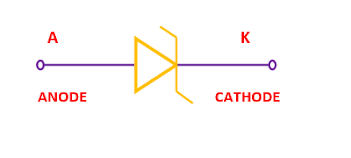
Avalanche Diode Symbol

V-I Characteristic of the Avalanche Diode

The V-I characteristics of the Avalanche Diode are shown in the figure below. It shows that the Zener breakdown occurs at a breakdown voltage of nearly 4 V under reverse bias condition whereas, the avalanche breakdown occurs at a breakdown voltage of more than 6 V under reverse bias condition.


V-I Characteristics of an Avalanche Diode


What is an Avalanche Breakdown Voltage?

In a diode, when we increase the reverse bias voltage across a P-N junction then the reverse saturation current remains constant up to a certain limit but If further increase reverse bias voltage then it will breakdown the P-N junction, and hence, the reverse current increases sharply to a high value. This critical value of reverse bias voltage at which the reverse current increases sharply is known as the avalanche breakdown voltage.

Usually, the avalanche breakdown occurs at a breakdown voltage of more than 6 V. 

When an Avalanche Effect or Avalanche Breakdown Occurs?

The avalanche effect or the avalanche breakdown occurs in lightly doped p-n junction diode under the reverse bias condition.

Comparison Between Zener Breakdown and Avalanche Breakdown

The difference between the Zener breakdown and the avalanche breakdown is given in the table below.

Avalanche Breakdown

Zener Breakdown

Avalanche Breakdown occurs in a lightly doped P-N junction diode under the reverse bias condition.

Zener Breakdown occurs in a heavily doped P-N junction diode under the reverse bias condition.

Avalanche Diode has a wider (thick) depletion region.

Zener diode has a narrower (thin) depletion region.

The Electric field set up across the depletion region is weak due to a wide depletion region.

The Electric field set up across the depletion region is strong due to a narrow depletion region.

The Avalanche Breakdown occurs due to the collision of accelerated charge carriers with the adjacent atoms and due to carrier multiplication.

The Zener Breakdown occurs due to the breaking of covalent bonds by the strong electric field across the junction.

The Avalanche Breakdown occurs at a breakdown voltage of more than 6 V.

The Zener breakdown occurs at a breakdown voltage of less than 4 V.

The breakdown voltage increases as junction temperature increases.

The breakdown voltage decreases as junction temperature increases.

The temperature coefficient is positive.

The temperature coefficient is negative.

The avalanche breakdown is not reversible.

The Zener Breakdown is reversible.


Is Avalanche Breakdown Reversible or Not?

The Avalanche breakdown is not reversible. As the Avalanche Breakdown occurs due to the collision of accelerated charge carriers with the adjacent atoms and due to carrier multiplication. Whereas, Zener Breakdown occurs due to the breaking of covalent bonds by the strong electric field across the junction. Hence, the Zener breakdown is reversible.
Avalanche breakdown can be reversible if we connect the resistor in series with the diode.

How the Avalanche Breakdown Is Not Reversible and the Zener Breakdown Is Reversible? 

When a P-N junction of the diode is in Zener breakdown condition and if we decrease the external reverse bias voltage, then the P-N junction is not damaged and returns to its initial state. Hence, the Zener breakdown is reversible.
whereas, if a PN junction of the diode is in avalanche breakdown condition and if we decrease the reverse bias voltage, then the P-N junction can’t return to its initial state. Hence, in the avalanche breakdown condition, the P-N junction is permanently damaged. Hence, the Avalanche Breakdown is not reversible.

Applications of an Avalanche Diode

Some applications of the avalanche diode have been discussed below.

  • The Avalanche diode can be used to protect the circuit. In a diode, when reverse bias voltage rises up to a certain limit then an avalanche effect starts in the diode at a particular reverse bias voltage and the breakdown of the diode occurs due to the avalanche effect.
  • The Avalanche diode is used to protect the circuit against unwanted voltages.
  • The Avalanche diode is used as surge protectors to protect the circuit from surge voltage. 


Analog and Digital Instruments - What they Are? (Comparison and Advantages of Digital Instruments over Analog Instruments)

Analog and Digital Instruments What are Analog Instruments? The signals which continuously vary and take infinite values for a given range a...